ANSYS Sherlock PCB reliability
Defense electronics must survive extreme environments. A printed circuit board (PCB) in a missile guidance system, a satellite module, or a radar unit faces intense heat, random vibration, mechanical shock, and wide temperature swings. If that board fails, the mission fails.
Traditional testing methods catch failures after hardware is built. That means expensive rework, long delays, and in defense programs, cost overruns that are hard to justify. The better approach is to predict failures before a single board is manufactured.
This is exactly what ANSYS Sherlock PCB reliability analysis delivers. Sherlock is a dedicated electronics reliability software tool from ANSYS. It uses physics-of-failure methods to simulate how PCBs and electronic assemblies behave under real-world stress conditions. Engineers can go directly from ECAD design files to detailed reliability analysis without building physical test hardware.
This blog explains how Sherlock works, why it matters for defense and aerospace programs in India, and how defense electronics suppliers can use it to meet MIL-SPEC reliability standards faster and at lower cost.
What Is ANSYS Sherlock and Why Does It Matter?
ANSYS Sherlock is a PCB failure analysis software tool designed specifically for electronics reliability. Unlike general-purpose finite element analysis (FEA) tools, Sherlock is built to understand the language of electronics design. It reads ECAD files directly, recognizes component types, board stackup data, and material properties, and then builds a simulation model automatically.
This matters because traditional FEA tools require engineers to manually build detailed PCB models. That process takes days or even weeks. Sherlock cuts that effort down to hours. Engineers import their ECAD file, define the environment the board must survive, and run the simulation. Sherlock then predicts where failures will occur and how long the board will last.
Sherlock is part of the broader ANSYS electronics reliability workflow. It integrates with ANSYS Mechanical for structural simulation and ANSYS Icepak for thermal analysis. This integration creates a complete multi-physics simulation electronics environment where thermal, structural, and reliability results all connect.
For defense programs supplying to ISRO, DRDO, or global military OEMs, Sherlock provides the simulation depth needed to meet strict qualification standards without relying entirely on physical testing.
The Core Problems with Traditional PCB Qualification
To understand why Sherlock is valuable, it helps to understand the pain points in traditional defense-grade PCB qualification simulation workflows.
Problem 1: Physical Testing Is Expensive and Slow
Building physical PCB prototypes for qualification testing takes time and money. For defense programs, each prototype cycle can cost hundreds of thousands of rupees. Environmental stress screening, thermal cycling chambers, and vibration tables add further cost. When a failure occurs late in testing, the entire design must be revisited.
Problem 2: Failures Are Found Too Late
Physical test campaigns happen at the end of the design cycle. By that point, changing the board layout, component selection, or stackup is costly. Printed circuit board reliability testing at this stage is a verification step, not a design tool. It confirms failures but does not prevent them.
Problem 3: Solder Joint and Thermal Failures Are Hard to Predict
Solder joint fatigue life prediction is one of the most difficult challenges in electronics design. Solder joints fail because of repeated thermal expansion and contraction cycles. The failure depends on the component package, the board material, the solder alloy, and the thermal environment. No physical test can quickly sweep through all combinations. Simulation can.
Problem 4: Vibration and Shock Analysis Requires Specialist Skills
Defense hardware faces random vibration and drop shock loads that standard design tools cannot model. PCB vibration analysis software must account for board natural frequencies, component mass effects, and lead fatigue under dynamic loading. Without dedicated simulation tools, engineers rely on conservative design margins that add weight and cost.
How ANSYS Sherlock Solves These Problems
Sherlock addresses each of these problems through a structured, automated simulation workflow. Here is a step-by-step look at the ANSYS Sherlock workflow for aerospace electronics manufacturers in India.
Step 1: Import ECAD Files Directly
Sherlock reads industry-standard ECAD formats including ODB++, IPC-2581, and Gerber files. When the file is imported, Sherlock automatically recognizes component placement, board dimensions, layer stackup, and material properties. There is no need to manually recreate the PCB geometry in a CAD tool. This is the foundation of the CAD to simulation PCB validation workflow.

Step 2: Define the Use Environment
Engineers define the operating environment the board must survive. This includes thermal cycling profiles (temperature range and cycle rate), random vibration power spectral density (PSD) profiles, mechanical shock inputs, and humidity conditions. For ISRO and DRDO PCB qualification programs, these profiles are typically derived from MIL-STD-810 or ECSS standards.
Step 3: Run Physics-of-Failure Analysis
This is where Sherlock’s core value lies. Sherlock runs component-level reliability simulation using physics-of-failure (PoF) models. These models are based on decades of electronics failure research and empirical data. Sherlock calculates the following for each component on the board:
- Solder joint fatigue life under thermal cycling (thermal cycling simulation PCB)
- Lead fatigue life under random vibration (random vibration analysis electronics)
- Failure risk from conductive anodic filament (CAF) formation between PCB traces
- PCB warpage under thermal load (PCB warpage simulation ANSYS)
- Component survivability under drop shock and mechanical impact
- Thermal derating analysis of individual components against their rated limits
Each result is mapped back to the PCB layout. Engineers can see exactly which components and which solder joints are at highest risk of failure. The visual output makes it easy to prioritize design changes.
Step 4: Integrate with ANSYS Mechanical for FEA Depth
For cases requiring more detailed structural analysis, Sherlock exports the PCB model directly to ANSYS Mechanical. This enables high-fidelity finite element analysis of the board assembly under vibration, shock, and thermal load. The integrated ANSYS electronics reliability workflow means engineers do not need to rebuild models when moving between tools.
Step 5: Generate Qualification Reports
Sherlock produces detailed reliability reports that document analysis assumptions, failure predictions, and design life estimates. These reports support the printed electronics qualification workflow for MIL-SPEC programs and help defense electronics suppliers demonstrate compliance to program offices and certification bodies.
ANSYS Sherlock vs Physical PCB Testing for Aerospace Applications
Physical testing and simulation are not mutually exclusive. The goal is to use simulation to reduce the number of physical test cycles required. Here is how the two approaches compare.
Comparison: Physical Testing vs ANSYS Sherlock Simulation
Time to first result: Physical: 8-16 weeks | Sherlock: 1-3 days
Cost per iteration: Physical: Very high (hardware + lab) | Sherlock: Low (software only)
Design iteration speed: Physical: Slow | Sherlock: Fast
Failure root cause visibility: Physical: Limited | Sherlock: Component-level detail
Ability to test all scenarios: Physical: Limited by budget | Sherlock: Unlimited
MIL-SPEC report generation: Physical: Manual documentation | Sherlock: Automated reporting
The ANSYS Sherlock cost savings vs prototype testing for PCB validation become significant when you consider that most defense PCBs require three or more prototype iterations before qualification. Each saved prototype cycle translates directly into schedule recovery and budget savings.
Key Failure Modes Sherlock Addresses for Defense PCBs
Solder Joint Fatigue Under Thermal Cycling
Defense electronics experience wide temperature swings during operation and storage. ANSYS Sherlock thermal fatigue analysis uses the Engelmaier model and other fatigue life models to predict how many thermal cycles a solder joint can survive before cracking. Engineers can compare different solder alloys and component packages to select the most reliable combination.
Random Vibration and Mechanical Shock
Launch vehicles, aircraft, and ground vehicles all generate vibration and shock loads. Sherlock runs drop shock simulation defense hardware analysis to predict which components will exceed their structural limits. The tool calculates board flexure under vibration and maps the bending strain across all component lead connections.
Conductive Anodic Filament (CAF) Growth
CAF failure is a reliability concern in high-density PCBs used in humid environments. Conductive anodic filament (CAF) failure simulation in Sherlock evaluates the risk of electrochemical migration between PCB vias and traces. This is particularly relevant for electronics used in maritime, tropical, or high-altitude defense environments.
Component Thermal Derating
Thermal derating analysis of components checks whether each part on the board operates within its rated temperature range when the board is running at full power. Sherlock identifies over-stressed components before they become field failures. This analysis feeds directly into the ANSYS electronics reliability workflow for both the PCB and the wider system.
ANSYS Sherlock for ISRO and DRDO PCB Qualification in India
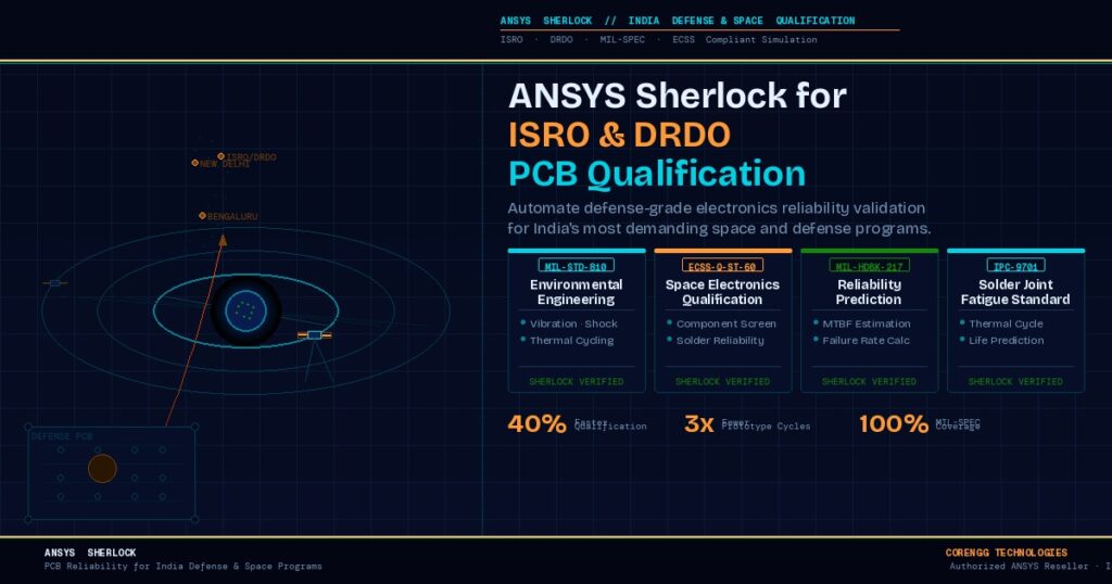
India’s space and defense electronics sector is growing rapidly. ISRO’s satellite and launch vehicle programs, DRDO’s advanced missile and radar systems, and the growing private space ecosystem all demand high-reliability electronics that meet strict qualification standards.
For Indian defense electronics suppliers, the challenge is to demonstrate compliance with MIL-STD-810, MIL-HDBK-217, ECSS-Q-ST-60, and other relevant standards while keeping development timelines competitive. How defense electronics suppliers use ANSYS to meet MIL-SPEC reliability standards comes down to using Sherlock early in the design cycle, not just at the qualification gate.
When Sherlock is used from the first schematic layout, engineers can make reliability-aware decisions about component placement, board stackup, and thermal management before committing to a PCB layout. This shifts reliability engineering from a qualification activity to a design activity.
To automate PCB reliability analysis using ANSYS Sherlock in India, companies need access to the software, training, and application support. Working with an authorized ANSYS reseller in India provides all three, along with localized knowledge of the defense supply chain and qualification requirements.
Best Simulation Software for Defense-Grade Electronics Reliability in India
When evaluating the best simulation software for defense-grade electronics reliability in India, three capabilities matter most: physics-of-failure based analysis, ECAD integration, and multiphysics connectivity to structural and thermal solvers.
ANSYS Sherlock leads in all three areas. No other tool in the market offers the same combination of automated ECAD import, comprehensive component-level reliability simulation, and direct integration with ANSYS Mechanical and ANSYS Icepak.
For companies already using ANSYS tools for structural or CFD simulation, adding Sherlock to the workflow is straightforward. The shared ANSYS Workbench environment means data passes between tools without manual reformatting. This is the core advantage of the electronics design validation aerospace defense workflow that ANSYS enables.
Competing tools typically require engineers to export and reformat data between separate analysis environments. That adds time, introduces error, and breaks the audit trail that defense qualification programs require.
How to Use ANSYS Sherlock for Defense PCB Reliability Validation: A Practical Summary
Here is a concise summary of how to use ANSYS Sherlock for defense PCB reliability validation:
- Import ECAD files: Load your ODB++ or IPC-2581 file into Sherlock. Component data populates automatically.
- Define use environments: Enter thermal cycle profiles, vibration PSD, shock pulses, and humidity levels from your program specification.
- Run PoF analysis: Sherlock calculates solder joint fatigue life, CAF risk, vibration damage, and thermal derating for every component.
- Review risk map: Identify high-risk components and solder joints from the visual board-level risk overlay.
- Modify and re-run: Change component selection, placement, or stackup and re-run in minutes to compare reliability outcomes.
- Export to ANSYS Mechanical: For deeper structural analysis, push the model to ANSYS Mechanical for full FEA validation.
- Generate qualification report: Produce a documented reliability report that supports your MIL-SPEC or ECSS qualification submission.
The Business Case: ANSYS Sherlock Cost Savings vs Prototype Testing
The ANSYS Sherlock cost savings vs prototype testing for PCB validation are measurable. Consider a typical defense PCB development program that requires three prototype builds before qualification approval. Each build cycle includes PCB fabrication, component procurement, assembly, and environmental testing. In India, a single prototype cycle for a complex defense PCB can cost between 5 and 20 lakhs depending on complexity.
If Sherlock identifies critical failure modes in the first design iteration, the team can correct them before the first prototype is built. This eliminates one or two prototype cycles entirely. Even in a conservative scenario where Sherlock reduces prototype cycles from three to two, the cost savings typically exceed the annual software license cost in the first program alone.
Beyond cost, schedule recovery is often the greater value. Defense programs operate on fixed delivery timelines. Saving four to eight weeks by eliminating a failed prototype iteration can mean the difference between on-time delivery and contract penalties.
Conclusion
ANSYS Sherlock PCB reliability analysis changes the way defense electronics teams approach qualification. Instead of discovering failures in a test chamber, engineers predict and fix them at the design stage. The result is fewer prototype cycles, lower development costs, faster qualification timelines, and electronics that perform reliably in the most demanding environments.
For Indian defense and aerospace electronics suppliers serving ISRO, DRDO, or global OEMs, Sherlock provides a clear path to meeting MIL-SPEC and ECSS reliability standards with greater confidence and less risk.
Corengg Technologies is an authorized ANSYS reseller in India. We help defense and aerospace engineering teams implement ANSYS Sherlock, provide hands-on application training, and offer ongoing simulation support tailored to your qualification program needs. Whether you are starting your first ANSYS Sherlock implementation or looking to expand your existing simulation workflow to cover electronics reliability, our team is ready to support you.
FAQ
Sherlock uses physics-of-failure models such as the Engelmaier fatigue model and Darveaux energy-based approach. It takes thermal cycle profile inputs and material properties to calculate the number of cycles to crack initiation for each solder joint on the board.
Physical testing validates a finished design against a set of conditions. Sherlock simulation predicts failures before the hardware exists. Sherlock can test unlimited design variants in days. Physical testing is limited by hardware cost and lab availability. The two approaches work best together, with Sherlock reducing the number of physical test iterations needed.
Yes. Sherlock supports the definition of custom use environments based on ECSS, MIL-STD-810, and other standards applicable to ISRO and DRDO programs. The generated reliability reports provide documentation that supports formal qualification submissions.
Corengg Technologies provides ANSYS software licensing, onboarding, application-specific training, and simulation support. Our team has experience supporting defense and aerospace electronics programs in India and can guide your team from initial ECAD import through to qualification report generation.